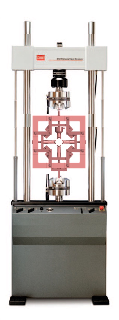
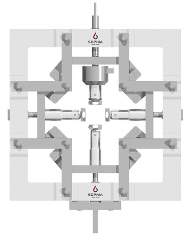
Biaxial Test Fixture has been developed for loading an in-plane specimen simultaneously in two principal directions.
- Fixture is designed for use with an universal testing machine
- Use of the fixture should require no modifications of the test machine
- Alignment of the fixture should be considered so that no bending moments or shear forces are transmitted through the specimen being tested
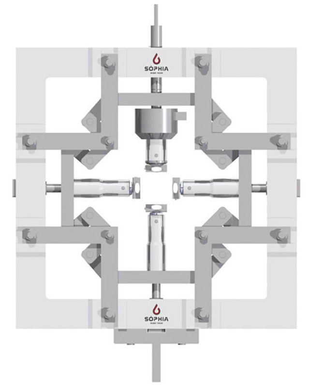
This mechanism can be adapted to any uniaxial tension test machine and thereby it reduces the cost of conducting tests on expensive machines.
This equipment provides a fixed structure and a mobile part made up of a mechanism that, through eight concave pushing crank, allows to distribute equally along the two orthogonal axes the load coming from a universal machine.
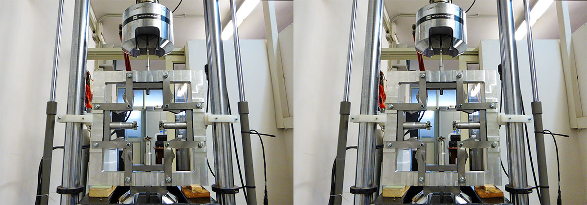
The mechanism is fixed on the moving crosshead of the machine by an adapter. During the excursion of the crosshead the crank rotation occur and vertical and horizontal grips moves accordingly, pushing or pulling the specimen. The load between two directions can be changed by changing the rod and the crank length.
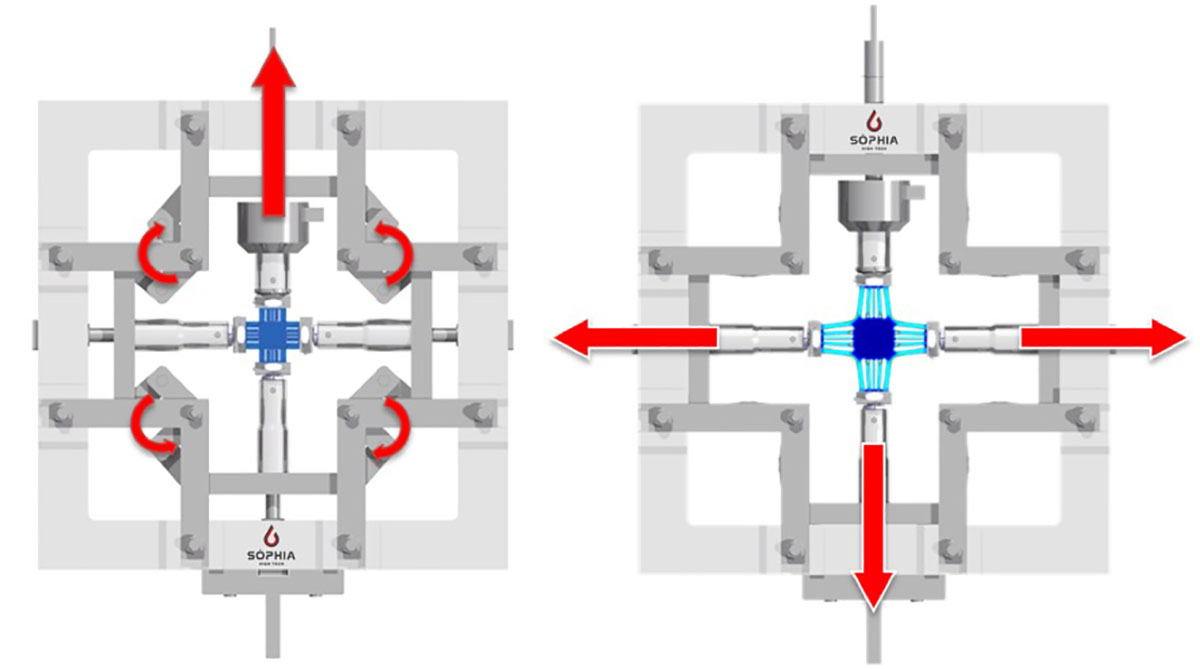
A cruciform specimen can be mounted in four grips. The vertical top grip is fixed to the load cell so that the uniform stress applied on each direction can be measured.
This mechanism has been designed to test a 100mmx100mm cruciform specimen with a stroke of 32mm. It is suitable for testing composite and rigid plastic materials.
In the table shown below typical characteristics of biaxial test are reported.
| FIXTURE CHARACTERISTIC | SPECIMEN | MATERIAL TESTED |
| Max Force applied: 5000N | Max width: 50mm | Polymers |
| Max Stroke: 32mm | Max thickness: 6mm | Polymer matrix composites |
